
The Donor Camera Search Goes Wrong
Last post ended with a prediction: "or whether I'm about to learn a whole new lesson about power delivery in a tiny space." Turns out that forecast was painfully accurate. The whole project hit a wall-one I should have seen earlier.
Remember how I thought about the Sony NEX series as my donor camera? Small enough and within budget, should have worked perfectly. But when I dug into the Sony Imaging Edge device list, I found something inconvenient: NEX cameras don't support PTP at all. No remote triggering, no shutter speed control, no ISO adjustment-nothing. That killed the whole plan.
The fallback was the Sony A5000 (ILCE-5000), which does support PTP and fits the budget. I already own an A6000, so I borrowed it to test the latency before committing to buy a 5000. The critical question: would shutter and ISO changes respond fast enough over PTP to feel real-time? I needed a response time under roughly 150ms-fast enough that I wouldn't notice lag when adjusting settings with physical rotary switches. The good news: it worked. Latency was solid.
But when I plugged it in to do that testing, something revealed itself that would have been a dealbreaker later.
The moment the USB connected, the screen went black with "Connected to PC" blinking on it. That's when it hit me: remember how I planned to get images sharp? Live-feed edge detection, cropping to a region of interest, running a Laplacian filter to measure sharpness, and showing a focus indicator LED in the rangefinder patch. I was going to tap the HDMI output, feed it to a capture card, then pass that video stream to the Raspberry Pi.
The problem: Sony's HDMI output is the camera screen. When the screen goes black over USB, the HDMI does too. And the A5000, A5100, and A6000 don't support live view over PTP. So I'd have a camera where I could trigger the shutter remotely-but I couldn't see a live feed to focus with, and I couldn't use my edge-detection system. The whole focus-indicator concept collapsed.
Switching to Canon EOS
After more research, I narrowed my options down to one choice: the Canon EOS series. Not ideal, sure-these SLRs are bulkier than rangefinders-but they had what I needed: built-in live view that works over PTP, and dirt-cheap used units. The 550D, 600D, 700D-all available for 30-100 € in decent condition. I bought a 600D for 60 € and figured I'd make it work.
But while I waited for it to arrive, my doubts started climbing.
Disassembling the FED 2
I didn't want to butcher the 600D without being absolutely certain of my plan. So first: actually open the FED 2 and see how much internal space existed. At least I could start measuring while waiting for the camera to ship.
There's a great YouTube channel by Alin Ciortea with a step-by-step FED 2 disassembly. Following along, I had the whole thing taken apart in under an hour. My research from earlier was spot-on-the Leica bottom-loading design meant everything came out cleanly. No cutting, no fighting with integrated mechanisms. Just screws, springs, and careful extraction.
The empty shell had roughly the space I'd calculated. But now that I was staring at the actual 600D specs and thinking about how its mainboard would sit in there, I realized the problem: the 600D's sensor stack and mainboard were going to be a tight fit-maybe even impossible with a battery packed in alongside.
The Battery Problem
Here's where things got complicated. The FED 2 is tiny-roughly 140mm × 80mm × 32mm. Inside that shell, I needed to fit:
- A Canon 600D mainboard and sensor stack
- At least one 1100 mAh battery for the camera
- Ideally a second battery for the Raspberry Pi Zero 2W
- Cables, and the Pi itself.
Sony FW50 batteries (the 600D's native power) are 48mm × 30mm × 18mm. Just barely squeezable if I had one. Two? Not a chance.
My first instinct was to extend the bottom of the FED 2 with a 3D-printed case. The FED 2 has a tripod socket on its base-I could drill through that, mount a battery pack externally, and run cables inside.
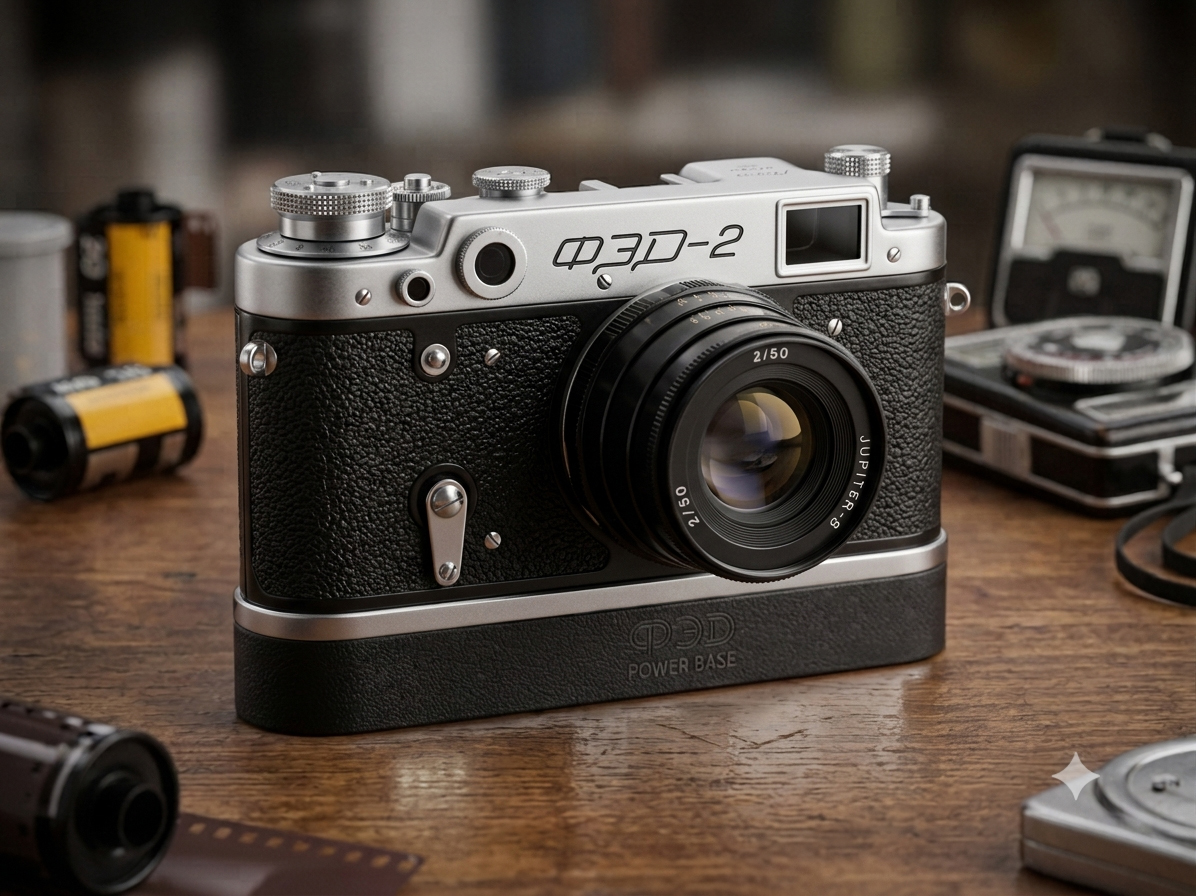
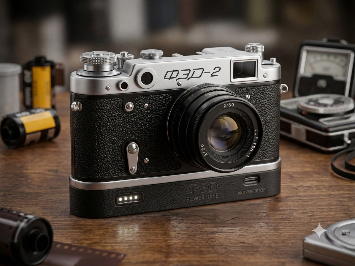
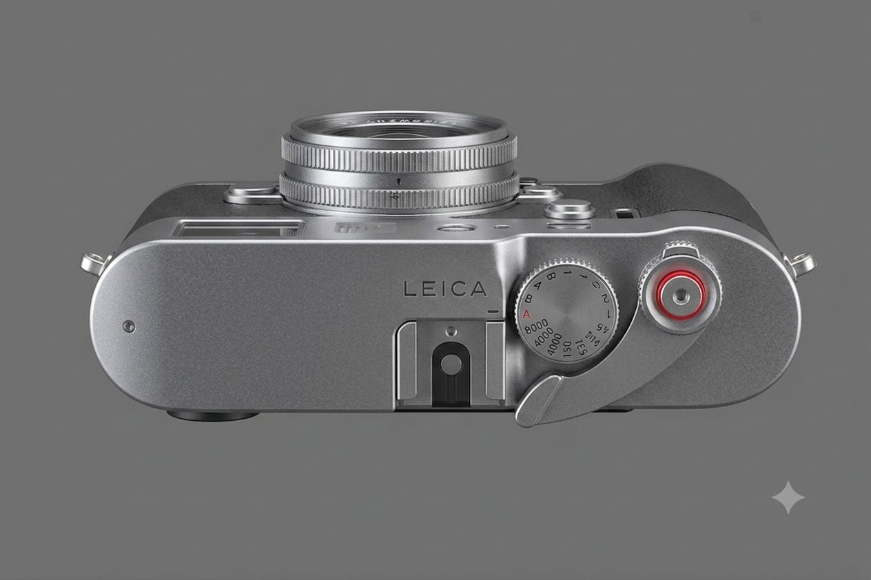
Concepts generated using Nano Banana 2 and adjusted using photoshop
Clever, right? Except I hit the next problem: how do I actually get power out of a Sony FW50 battery? They have a proprietary contact plate, and there's no simple connector. I considered harvesting the charging cable, but the whole approach felt fragile. And I'd need a power management board to monitor voltage and display battery status across two separate cells.
That's when I pivoted to LiPo batteries.
The Search for the Right LiPo
LiPo (Lithium Polymer) batteries are standard in the RC hobby-affordable, high energy density, and available in countless configurations. The naming is straightforward: a "1S" battery has one cell (3.7V), "2S" has two in series (7.4V), "3S" three cells (11.1V), and so on. For my 600D, which needs about 7.2 volts, a 2S LiPo was the obvious choice.
But I needed something specific: a 2S LiPo that fit within the 32mm width constraint of the camera.
The problem: standard RC LiPos start at 34-35mm. Every hobby-grade battery I found was too fat. I could have tried building my own 2S Li-ion pack instead-Li-ion cells are cylindrical and physically smaller than LiPo pouches. But that would have meant sourcing two separate 18650 or 21700 cells, hand-soldering a balance connector, adding protection circuits, and hoping the whole assembly didn't short or catch fire in a confined space. Not ideal for something I'm going to be carrying around and shooting with every day.
That's when I discovered receiver LiPos-a specialized category designed for smaller RC receivers and drones. They're lower capacity and lower discharge rate than their hobby-grade cousins, but that's actually perfect for this use case. A camera doesn't need the 50C+ discharge rates that racing drones demand. And unlike hand-assembled Li-ion packs, receiver LiPos come as pre-built, pre-tested units with proper protection already built in.
After hours of searching through hobby electronics suppliers, I found the Sunpadow Receiver Li-Po 7.4V 2400mAh 5C-and it would fit. Dimensions: 83mm × 28.8mm × 15.3mm (width was within spec). Energy density: 2400 mAh would power the camera and Pi for a solid shooting session. Price: about 25 €.
The 5C discharge rate tells you the maximum safe current the battery can deliver continuously. It's calculated as: capacity × C-rating = max current. So for a 2400mAh battery with 5C: 2.4A × 5 = 12A maximum.
For my actual setup, the power draw breaks down like this:
Peak draw (everything at max):
- Canon 600D during active processing: ~2-3A
- Raspberry Pi Zero 2W (full load): ~0.5-1A
- LEDs and misc: ~0.1-0.2A
- Total: ~3.5A maximum
But that's not realistic for actual shooting. The camera isn't constantly processing-it's mostly idle between shots. Average draw during normal shooting is much lower:
Average draw (typical shooting session):
- 600D average (mostly idle): ~0.8-1.2A
- Pi Zero average: ~0.3-0.5A
- LEDs: ~0.1A
- Average: ~1.2-1.8A
With 2400mAh at an average draw of 1.2-1.5A, I get roughly 1.5-2 hours of shooting. Closer to 3-4 hours with lighter use (lower average draw). That's solid for a personal project camera.
What C-rating do I actually need? The formula is: Current ÷ Capacity = C-rating. So:
- At 1.2A average: 1.2A ÷ 2.4A = 0.5C
- At 1.8A average: 1.8A ÷ 2.4A = 0.75C
I need somewhere between 0.5C and 0.75C to safely power my setup. The Sunpadow I found is 5C-which means I have a 6-10x safety margin. That's massive overkill, but it also means the battery will last for many charge cycles without degradation, and I'm nowhere near stressing it. Perfect for something I'll be using and charging regularly.
You might notice how I work through problems: research deeply, explore multiple paths, calculate everything, iterate on solutions. I always try to find the straightforward way forward without unnecessary detours. That habit probably comes from my technical directing background-as someone who builds and designs for a living, I want to find the perfect, fastest, smartest solution. But here's the catch: that approach works great when you're solving a known problem. When the problem keeps changing-when you discover new constraints at every step-all that optimization becomes exhausting. Which is exactly what was happening.
Reconsidering the Whole Approach
At this point, I was staring at stacks of CAD files, battery specifications, and mounting calculations. And I had a thought that had been creeping in for days: Why am I doing this to myself?
The whole project started because I wanted the feeling of an old camera-the limitations, the mechanical focus, the rangefinder design. I loved the FED 2's aesthetic. But I'd spent weeks designing battery packs, measuring to the millimeter, and planning workarounds just to cram modern electronics into a shell 5mm too shallow.
What if I just... built the camera I actually wanted?
Looking for Alternatives
Before committing to custom builds, I searched for other rangefinder shells that might have more internal depth. Yashica, Kiev, Zorki, Zenit-the Soviet and Japanese brands all made hundreds of variants, each trying to be smaller than the last. That's the nature of rangefinder design: portability was a selling point. Nothing I found offered significantly more room than the FED 2.
The Yashica Electro 35 GSN caught my eye briefly-it's slightly larger-but when I found a disassembly video, it was clear: the film gate was molded directly into the case. No clean removal. More fighting, same constraint.
SLRs would have given me more depth, but aesthetically? I can't do it. A modern digital Frankensteining inside a boxy 1980s Canon body just feels wrong.
The Decision: Build from Scratch
At some point, the obvious answer hit me: I'm spending all this energy fighting someone else's constraints. I design and build for a living. So why not just... build what I actually want instead of forcing my vision into a box designed decades ago?
The answer was simple: I shouldn't try to fit my design into the FED 2. I should design my own camera from scratch.
If I design and 3D-print my own camera body from scratch, I can:
- Set the flange distance exactly where I need it (no custom extension tubes required)
- Choose the internal dimensions to fit my battery, mainboard, and electronics perfectly
- Design the ergonomics specifically for how I want to hold and shoot
- Control the aesthetic entirely-no compromises to work around
Yes, it's more work. But it's also the whole point of this "Frankenstein" project.
Designing from Inspiration
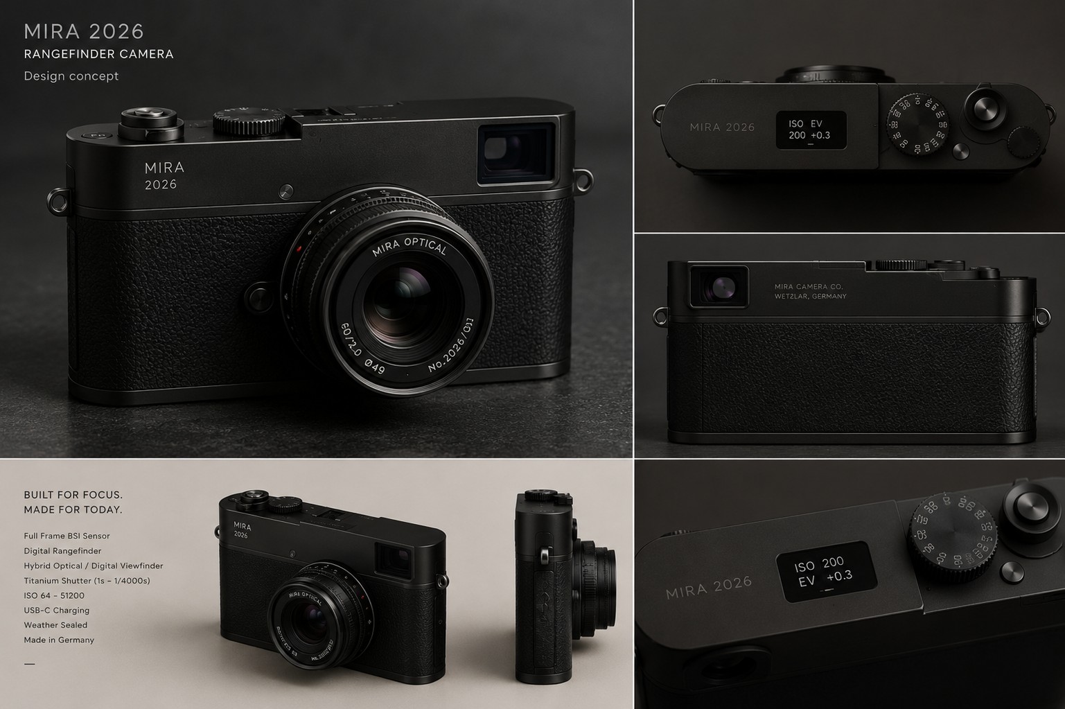
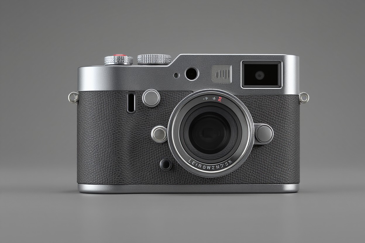
I started where I always do: brainstorming with reference images. Using Google's Nano Banana 2 to generate inspirational concepts, I collected dozens of shots-early Leica bodies, FED cameras, even some modern minimalist designs. The goal: a "sandwich" aesthetic with layered materials. Aluminum or similar for top and bottom (the "cold" feeling I wanted), leather or similar for the central band, minimalist controls, and absolutely no large screen.
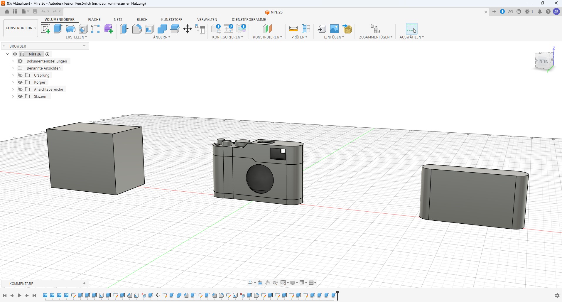
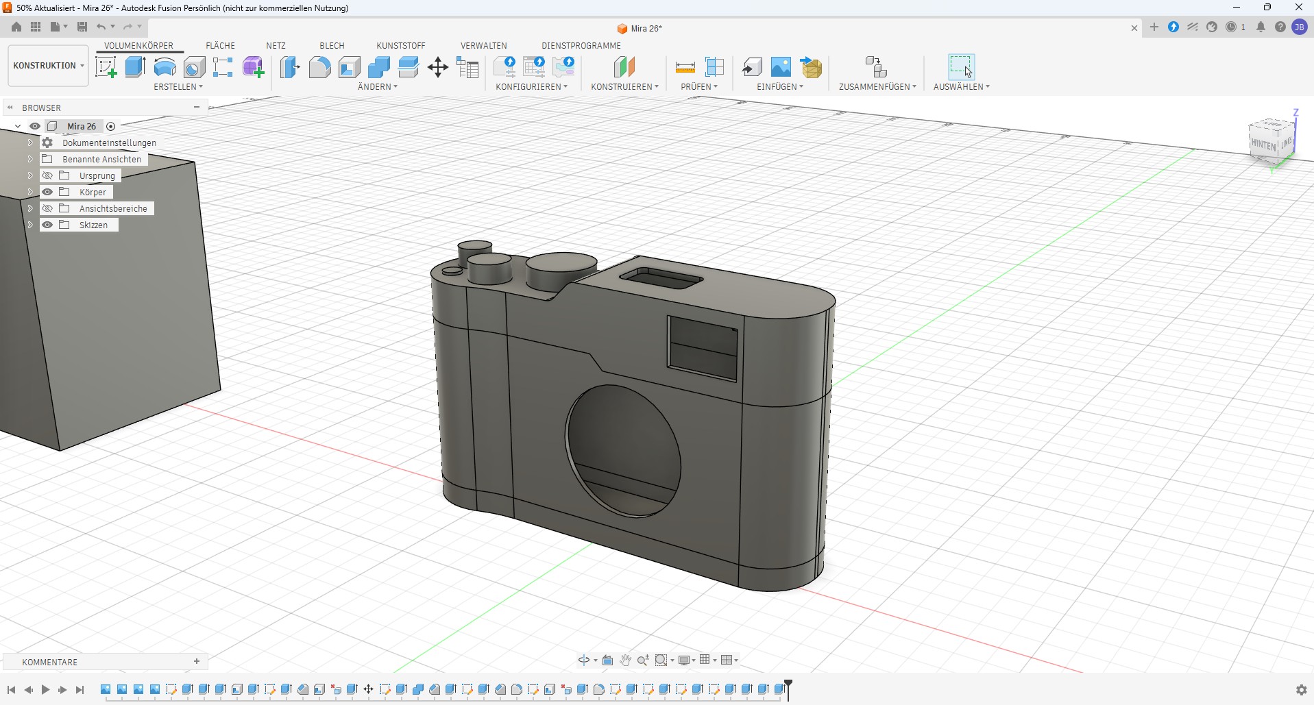
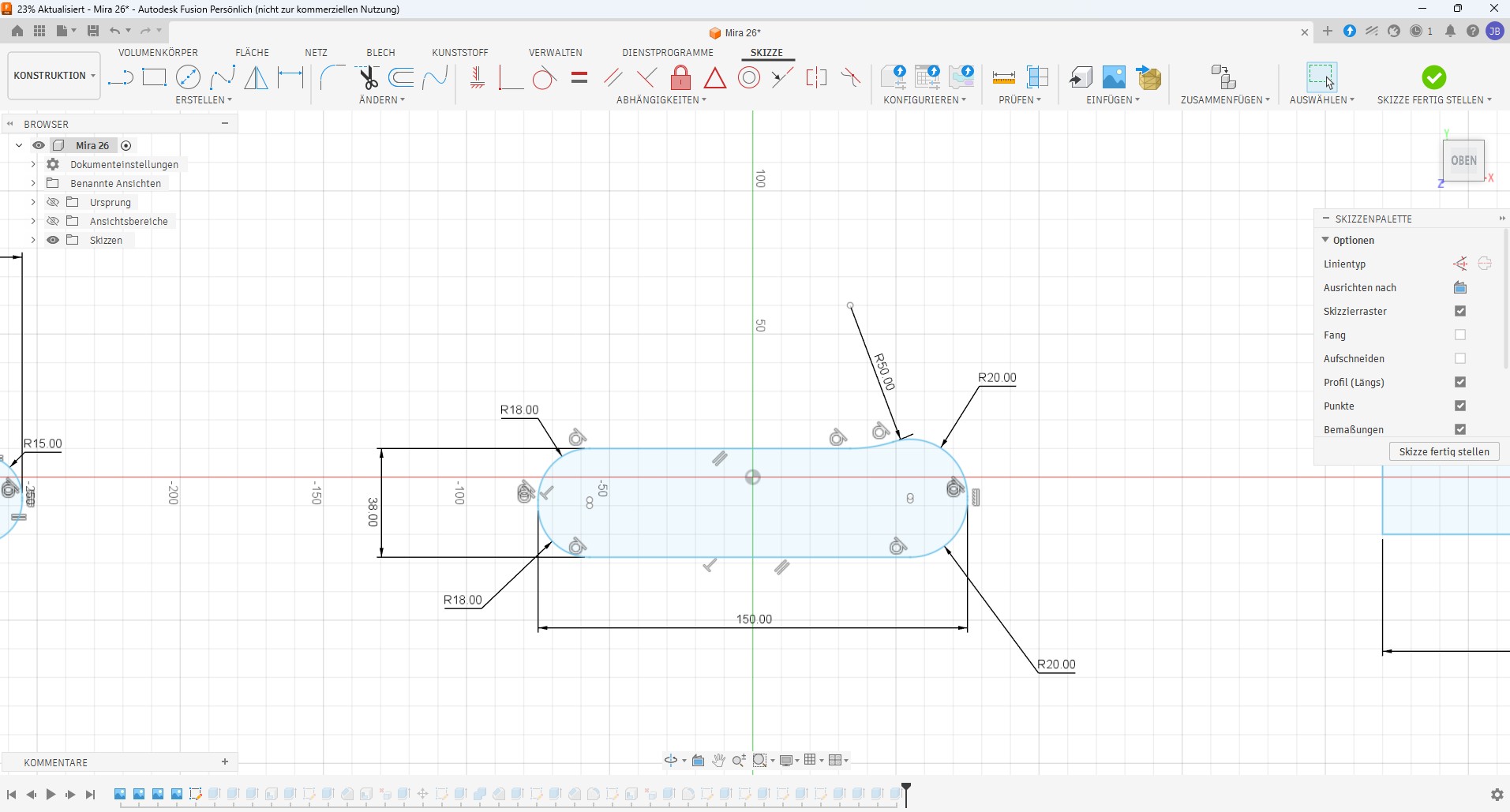
After iterations in PureRef (my go-to mood-boarding tool), I moved into Fusion 360 with a clear direction.
Designing the Details
Building a camera body isn't just about exterior shape. It's about where things go. Where should the shutter button sit? How does the size and shape of a hand grip affect where your index finger naturally lands? How much play should the focus ring have? These aren't trivial-they're the difference between a camera that feels good and one that feels clunky.
I noticed something I'd glossed over before: shutter buttons with progressive triggers are almost impossible to source. Most commercial buttons are either on/off. Cameras have them because they're custom-molded for each design. If I wanted the classic "light press to focus, full press to shoot" feel, I'd need to design one myself-probably using springs and different switching thresholds.
The Material Reality Check
Here's where idealism met practicality: I'd hoped to machine the top and bottom from aluminum. That "cold, solid" feeling of a professional tool. Then I checked prices.
CNC machining a custom one-off aluminum body? 400-600 €. And even then, the milling process leaves tool marks. To get it truly smooth, you'd need hand-finishing (sanding, anodizing, or hand-polishing), which adds more cost and time.
Okay. Aluminum was out.
I considered alternatives:
Method | Durability | Finish Quality | Cost | Time |
|---|---|---|---|---|
Galvanizing (electroplating with zinc) | Good | Bright, metallic look | Low | Low |
Cold casting (epoxy resin + metal powder) | Fair to good | High-quality finished look | Medium | Medium |
Resin printing (UV-cured) | Poor (UV degrades over time) | Excellent surface finish | Low | Low |
3D printing + post-processing | Good | Good with sanding/painting | Low | Medium |
CNC aluminum + hand-finishing | Excellent | Professional | Very high | High |
Injection molded plastic | Excellent | Perfect | Very high (needs mold) | High |
How each works:
- Galvanizing: An industrial process where parts are dipped in molten zinc or electroplated. Creates a durable metallic coating, but you need access to specialized facilities-not a DIY-friendly option.
- Cold casting: Mix epoxy resin with metal powder (bronze, copper, aluminum), pour into a mold of your 3D print, and let it cure. Creates a realistic metal appearance without actual machining.
- Resin printing: Instead of FDM plastic, print with UV-cured liquid resin for perfect surface finish straight out of the printer. Problem: the resin degrades under sunlight, so it's not durable for a camera you'd carry outside daily.
- 3D printing + post-processing: Print in durable plastic, then sand smooth, fill layer lines with filler, prime, paint, and clear coat. Old-school model finishing-labor-intensive but proven.
- CNC aluminum: Machine solid aluminum on a CNC mill. Produces perfect tolerances and professional finish, but the setup cost and material waste make it prohibitive for one-off builds.
- Injection molded plastic: Create a steel mold and run plastic through an injection molding machine. Perfect finish, but requires a mold ($5-10k+) that only makes sense if you're producing thousands of units.
Each had trade-offs I didn't want to live with-except one: 3D print in ASA (or nylon-carbon for the middle band for extra strength), then finish it the way I've learned restoring my vintage car: sand, fill, prime, paint, clear coat.
It won't have that metal-cold feeling. But it'll look intentional, feel substantial, and be durable. And honestly? After all this work, a camera that feels like a camera matters more than what it's technically made of.
The Prototype Phase
With the design nearing completion in Fusion 360, my next step is printing a prototype in PLA-just to hold it in my hands, confirm button positions feel right, and make sure the ergonomics work before committing to a finished material and finish process.
That's where we are now. The Frankenstein project evolved from "fit modern tech into an old shell" to "design the perfect shell for the modern tech." Not what I planned, but probably exactly what I needed to do.
Next time: the prototype in hand, what it reveals about ergonomics and button placement, and how the final camera actually comes together.